
Fuel Gauge 1800 Information and Notes
First published: Nov 2019 R. Kwas Revisions On-Going
[Comments Added]
Troubleshooting Notes
Fuel Sender Notes
Late 1800 (Injected)
Fuel Gauge [Wiring Diagram excerpt only.]
Links
Link to 122 Fuel Gage Notes, including troubleshooting: https://www.sw-em.com/Fuel%20Gauge%20Notes.htm
-----------------------------------------
The Smiths supplied 1800 fuel gauge (early, carbureted) is different from both 122 (based on the VDO supplied Drehspulinstrument) gauge (but not in operating Principle, see below!) and later (injected) Voltage Stabilizer associated gauges of the E and ES vehicles, therefore these three gauges types must be considered separately.
Slight variation in the face exist between the pre Chassis No. 7000, and post Ch. 7000, but the internals of gauges are the same, and in operating principle, similar to gauge of the 122. See also: Drehspulinstrument
-----------------------------------------

A page from the Factory Manual [correction for Fig. 2.3: Connection for
Ignition Power (not "positive terminal of battery"!). Fuel Gauge is
an Ignition function...why would you want it ON all the time, draining
the Battery? You wouldn't!...more auto-electrical wizardry courtesy of
Lucas? ]

1800 Fuel Gauge and circuit detail.
Full Indication: With Ignition ON, indication at Gauge should correspond to Fuel Level in Tank, but if it goes to Full, and stays there, even if Tank might be something less than full, it indicates an open connection somewhere, anywhere in the Sender line...from the wiring itself (rare but possible), the connection to chassis (including Sender electrical connection to Tank, and Tank electrical connection to Chassis), or within Sender itself.
If an Indication of Empty occurs (even with a Tank known to not be empty!), it can be that Gauge is not powered (open power or chassis connections), OR a Sender cable shorted to chassis, or even a non buoyant Float (see below!).
------------------------
As noted, 1800 and 122 instruments are similar only in operating principle. Picture below shows two Magnetic Coil Assemblies fixed to the housing, and generating magnetism at right angles. In the 122 instrument, they are part of the rotating Needle Assembly, see: Drehspulinstrument. Range of Resistance of the Sender does differ between the two instrument suppliers. See below!
Subsequent pictures by James R. and used with his kind permission:
[Very apparent in the following picture is also the Instrument Chassis connection which has been shown to be quite important! See: http://www.sw-em.com/Two_Wrongs_Make_a_Right!.htm ]

What the 1800 Fuel Gauge looks like from the business end, installed in a
Dashboard. Red/White wires are Instrument Lighting (Lamp in holder is a
friction-fit, and simply pulls out, for checking or bulb replacement),
(Double) Greens are Ignition Power from Fuse 2, to
B Terminal of Instrument, Green/Black is the Sender
connection to T Terminal of
Instrument, and (double) Blacks visible are some instrument chassis connections
(these are quite important for function of instrument, and may be located on Fuel Gage, or elsewhere)...depends on if it was raining
that day in Britain...
Reference also Wiring Diagram 1800: https://www.sw-em.com/Wiring_Diagrams_and_Related.htm#1800_Wiring_Diagram

Tools used to gently nibble (by bending) away at the Chrome bezel to allow gentle
removal of it, and gauge face (notice the generous and repetitive use of the
word gentle here...this is not by accident!). Note evidence of the bending on the instrument
edge to allow this. Note also slotted holes (at
Yellows) for precise position
adjustment of the Magnetic Coil Assemblies during calibration (see text below!).
There is evidence of a white lacquer on securing nuts. Don't loosen or
reposition these, but verify securing nuts are snug and have a dab of locking
paint. In the case of James' instrument, something in this system failed,
allowing coil assemblies to move out of position, which caused a complete
failure (non-function, but not terminal/death!) of the instrument.

Internals of gauge exposed.
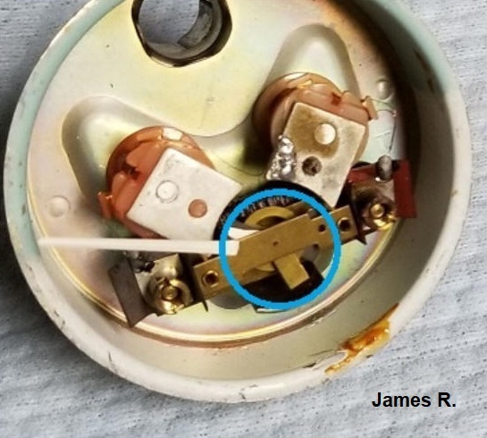
Blue circle highlights movement
arc of Needle Assembly, and matching arcs on the endplates of Magnetic Coil
Assemblies are clearly evident. Precise position of these determines
magnetic influence on the Needle Assembly and instrument calibration. They
were positioned and locked into place at the factory, and should not be moved by
mere mortals!
-----------------------------------------
Although the operating principle of the Amazon and 1800 Fuel Gauges is similar, the operating range of the 1800 Sender, at 3 Ohms (Float Down!) - 80Ohms (Float Up!), is different from that of the Amazon Sender.

1800 Tank Sender (Replacement type with plastic Float)
From the Brickboard Thread: Rusted out float on P1800 Smiths Fuel Sender 1800 1964:
https://www.brickboard.com/RWD/volvo/1677421/1800/rusted_float_p1800_smiths_fuel_sender.html
Pictures by J Graham Coutt.

The way JG found his Sending unit after removal from Tank.
Symptoms were
an Empty fuel level indication on gauge, even with a full tank.
That makes
sense, as the Float clearly was low in the buoyancy department.

JG's solution was to fit a brass float originally from a Mustang sender.
Coil of resistance wire in the upper compartment is apparent.
While Sender is on the bench, cleaning and inspection of the slider contact area are good practice, as is lubing this (wear) area with some Mobil 28 synthgrease. This grease is light in body, so easily displaced by the Slider allowing normal operation, but serves to lube the Slider contact area, minimizing wear.

Close-up of the Sender showing coiled length of resistance wire.
Highlighted in Yellow is the Slider, which is connected to the Float by way of the
rod,
which can be bent slightly to adjust gauge indication.
-----------------------------------------
PLACEHOLDER FOR LATE 1800 (E and ES) FUEL GAUGE NOTES (fitted in vehicles with Fuel Injection and Voltage Stabilizer):
Until I can add further details on the later version instrument, supplied by VDO, here is a Wiring Diagram excerpt of the Fuel Gauge and associated wiring. Note that Fuel gauge is one of the three Instruments supplied by the (cycling) output of the Voltage Stabilizer (Item 26), so function is similar to Smiths gauges only...troubleshooting will be somewhat different!

1800E and ES Fuel Gauge, Item No. 27, supplied by Fuse 4 with
Blue wire, by way of VStab (28).
-----------------------------------------
Thread where James R. repairs a non-functioning 1800 Fuel Gauge (early, carbureted): https://forums.swedespeed.com/showthread.php?610015-Fixing-P1800S-fuel-gauge
Apparently, the Magnetic Coil Assemblies on his gauge became dislodged and were out of position...he notes: "There was also a circle at the base of the needle with a similar diameter of the crescents, but my crescents were no where near lined up with the base of the needle. ").
My response to that thread
"Those pieces with the crescent shapes are the two Magnetized Coil Assemblies (at right angles to each other, this is the basis of both the 122 and 1800 instruments. Note in the 122 instrument, the coils are part of the rotating armature, in the 1800 instrument, they are fixed to the instrument case. See: https://www.sw-em.com/Fuel%20Gauge%2...spulinstrument), which act upon the Needle (more specifically, what the Needle is mounted to)...it sounds like mechanical securing of those coils became dislodged, so the magnetism was out of place and because of this, ineffective to work on the Needle as intended. By moving the poles to where it seemed they should be, you have brought back the function, but I expect the calibration will have less than its original accuracy and should not to be highly trusted until you get a few tank-fulls of experience with it! Congrats on the repair!"
------------
Link to another thread: http://forums.swedespeed.com/showthread.php?547874-Gas-tank-level-replacement-recommendations&p=6709266#post6709266
-----------------------------------------
Link to Document published in 1966: Smiths - The Care of Instruments
------------
Related to Reliability of Smiths Gauges:
Question: Where did workers fired from the Lucas factory go?
Answer: Down the street to the Smiths factory.
-----------------------------------------
External material sources are attributed. Otherwise, this article is Copyright © 2019-2022 Ronald Kwas. The terms Volvo, VDO, and Smiths are used for reference only. I have no affiliation with any of these companies other than to present my experience, and highly opinionated results of the use and care of their products, for the purpose of helping other owners keep their vehicles on the road, safe and reliable, and including ridiculing Lucas automotive electrics...because they brought it on themselves, so truly deserve it! (Reference Example: Proving Everything Bad you Ever Heard About Lucas) The information presented is my own, and can be used or not, or ridiculed and laughed at, at the readers discretion. As with any recipe, your results may vary, and you are, and will always be, in charge of your own knuckles, and future!
You are welcome to use the information here in good health, and for your own non-commercial purposes, but if you reprint or otherwise republish this article, you must give credit to the author or link back to the SwEm site as the source. If you don’t, you’re just a lazy, scum sucking plagiarist…so The Boston Globe wants you! As always, if you can supply corrections, or additional objective information or experience, I will always consider it, and consider working it into the next revision of this article...along with likely the odd metaphor and maybe wise-a** comment.
